

|
Complete Radio Service and Speedy Too. |
|
Majestic Radios |
|
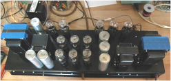
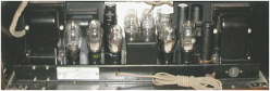
The restored 1934 25 tube Zenith 1000Z Stratosphere console radio Below, the new power supply amplifier designed and built by Majestic Radios and original receiver chassis before restoration. |
|
Featured Restoration 1934 Zenith Stratosphere |
|
1934 Zenith 1000Z Stratosphere 25 tube radio electronic restoration project July 2008
Earlier this year (2008) NMRCC member bought a Zenith Stratosphere, its cabinet was in beautiful shape and it had the radio receiver chassis, but it was missing the power supply/ audio amplifier chassis, all three speakers, the dial decorative bezel and all the knobs. The cabinet and bezel restoration story is a book all by itself and I’m going to leave that story for the owner to tell.
I offered to help my friend with the power supply/amplifier (PS/A) electronic design, securing of the transformers and chokes, and wiring. The owner bought the original Zenith service manuals, they included parts lists and schematics but did not include power transformer and choke design data, reverse engineering went into high gear. Through some extensive research and friendships he was able to get a tracing of the top of the PS/A so he was able to get a dimensioned drawing together and get a machine shop to fabricate the steel chassis with all the original punched hole locations. The chassis was also copper plated, which turned out to be a good idea since all the handling would produce rust. There were a few problems with the tube socket hole diameter which took a lot of filing.
I took the Zenith documentation and started the reverse engineering for specifying the two power transformers and two choke specifications. Here is the procedure I used: (1) I took all the 6.3VAC filaments and added up the total current (2) there are three 5Z3 rectifiers that ultimately I had to change to 80s because of lower filament current, I discuss this change later (3) estimated the radio receiver chassis B+ current draw at 125-150mA. The receiver chassis audio driver plates had 270VDC on the plates (4) the audio power amplifier located on the PS/A chassis uses eight 45 triode tubes which when biased at -63VDC draw an average 36mA each which is 288mA total plate current at 330VDC plate voltage.
I needed to find two power transformers able to deliver the DC voltages and current, and also provide 6.3VAC at 5A, 5VAC at 6A, 2.5VAC at 12Amps, and had 300-350VAC secondary’s for the B+ supplies. The filter chokes were easy since Zenith specified two 10H choke. I specified 10H 300mA and 10H 150mA chokes. I took a quick look at what Antique Electronic Supply and Radio Daze websites. Both had Hammond Manufacturing transformers and chokes that would work. I also needed two AC Line filter chokes, I used 8mH at 2A and we needed a 50Watt audio output transformer to match the 3.3k plate load; they had everything. A few days later we positioned the transformers and chokes on the PS/A chassis and everything looked very original to the 1933 Zenith design.
After some design work, estimations and calculations I designed the voltage divider used for 100VDC receiver screen voltages and 63VDC used for the 45 tube bias, more about that later. The speaker field coils checked out fine since they are part of the power amplifier power supply. The owner had purchased two old 12” Jensen loudspeakers that had 250-300 Ohm field coils and that appears to be correct for the 300mA power supply. The “Q” tweeter is a very rare horn tweeter that was believed to be replaced later with a 4” Jensen cone tweeter and it also had a 250-300 Ohm field coil. Unable to find a “Q” tweeter at any price a 4” Jensen from a Scott radio that was cosmetically identical but has a 1,200 Ohm field coil so a 350Ω resistor will have to be placed across the field coil to keep the excitation and supply voltage close to specifications. The two 12” woofer field coils are in series in the 300mA B+ supply and the 6” tweeter is in the radio chassis B+ supply. The 8µF 500V electrolytic cans are only cosmetic. The 5Z3 has a 3A heater which was too much for the available transformers; I decided to use 80s |

|
which have a 2A heater and adequate plate current capability for the job. That proved to be a okay choice since all voltages and current required were met.
The Testing and Burn-in (and NO-Smoke) I completed the wiring of PS/A chassis and connected up to a temporary audio driver transformer to the grids of the 45s along with the purchased output transformer to the plates. I tacked in 500Ω 20W resistors in place of the speaker field coils and installed a 2k 40W resistor across the receiver chassis power supply to simulate the radio chassis load of 150mA. I temporarily loaded the power amplifiers B+ supply with 1k 100W resistor and pulled all of the 45s. With the three 80s installed, I put 120VAC into the primaries and measured the DC voltages; all checked out fine. Then one by one I put one of eight 45s in a socket and measured and recorded the plate current. The used and NOS 45s that were purchased had plate current variations from 28mA to 41mA with 63VDC bias. I removed the 300mA load resistor, installed the 45s balancing the currents on each side of the push-pull circuit and powered it up again. All voltages were correct and the PA current was as expected. With audio from my Tektronix TM503 with a SG-505 oscillator and AA-501 distortion analyzer and 4” speaker connected across an 8Ω load connected to the output transformer, I had audio. Because of the voltage output limit of the SG-505 audio generator driving a high impedance driver transformer I was only able to get 12 Watts output power but the distortion (THD) was below 0.5% 30Hz. to 15kHz.; not bad for no feedback, transformer coupled amplifier.
The Zenith radio chassis needs all the capacitors replaced, all resistors checked [I don’t expect to find any of them to be out of tolerance since they are the carbon rod type with copper wire soldered to a metalized end on the carbon]. The audio driver transformer tested okay but the antenna matching coil has a mouse bite or two taken out of it but it looks like it’s the first layer of the outer portion of the coil so it’s easily repaired. That easy repaired ended up being a replacement of the coil. Zenith Stratosphere 1000Z Restoration Midway through I planned to replace all the film and electrolytic capacitors and the bad resistors; that turned out to be major project. I replaced 22 - 0.01uF 630V film capacitors, 8 - 0.047uF 630V film capacitors, 6 - 0.1uF 630V film capacitors, 3 - 0.47uF 630V film capacitors, a 20/20/20/40uF 450V electrolytic capacitor, 2 – 50uF 50V electrolytic capacitors and over 20 bad or out of tolerance resistors including some wire wound power resistors.
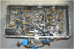
Now onto the fun part; I started too connected up the power supply amplifier to the radio chassis with an eleven conductor cable only to find that the schematic didn’t agree with what Zenith had built in 1935. After some more reverse engineering and modifications to the schematic all connections were made between the PS/Amp and receiver chassis. With AC power applied, switch on the volume control in the ON position the tubes came to life and smoke poured out of one new resistor in the RF amplifier plate build-outs. I found the short to be in one of the IF transformer cans, as shown to the left.
With all IF cans back in place I went on with the test. The DC voltages for the radio chassis needed to be 280-300VDC and I found it current to be 150mA, a little higher than expected. It also needed 100VDC at 40mA for the screens. The power transformer I had specified needed to be changed, so I found the correct |