


|
Complete Radio Service and Speedy Too. |
|
Majestic Radios |
|
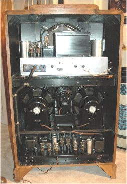
Rear view of the restored and reassembled Zenith 1000Z Stratosphere |
|
Featured Restoration |
|
Onto the final RF Alignment I went back to the radio chassis, did a mechanical alignment of the dial pointer, which is full CCW with the pointer parallel to the horizontal dial divider and proceeded to fully electrical align the receiver. I set my old General Radio 1001-A RF generator to 485 kHz., injected the RF signal into the grid of the mixer or 1st detector-oscillator.
with the IF bandwidth in the narrow setting I aligned the IF to peak AGC voltage keeping it around 2.5VDC by reducing the injected RF level. 2VDC is where the delayed AGC kicks in so I raised the signal injection to reach 2.5VDC which into full quieting in the Stratosphere. Now the full RF Alignment: I had already aligned broadcast band padder, Zenith has you connect the RF generator to the antenna terminals, set the generator to 600kHz. with 400kHz. modulation and then they want you to rock the tuning back and forth while adjusting the padder trimmer for maximum audio. I also adjusted the local oscillator trimmer and RF stages but I will recheck them again later. as you will see the alignment of the other bands does effect the broadcast band alignment.
First the Police band or as Zenith calls it “the Orange band” 1,450 - 4,200kHz., Zenith says set generator and dial to 3MHz. then adjust the oscillator trimmer “K”, peak 1st detector “G”, and RF trimmers “C”. With that done, 4uV RF produced 2VDC AGC voltage, that’s very good sensitivity.
Now the 4-10MHz. “Yellow band”, I set the generator and Zenith dial to 9MHz., adjusted oscillator trimmer “J”, peaked 1st detector “N” and RF trimmers “D”. 4-5uV produced 2VDC AGC voltage, that’s very good sensitivity too and WWV at 10MHz. came in fine also with just a clip lead for an antenna.
Now the 8.5-23MHz. “Red band”, I set the generator and dial to 21MHz. adjusted oscillator trimmer “I”, peak 1st det. “M”, and RF trimmers “E” and “F”. 5-6uV produced 2VDC AGC voltage, that’s very good sensitivity and WWV at 10MHz. came in fine again.
The 18-45MHz. “Blue band” has no adjustments and it did not work; the 6A7 local oscillator-mixer is most likely weak or gassy so I’ll come back to that problem later when I get another tube. I did find that the LO was not oscillating.
I went back to check the broadcast band and it was off at both ends of the dial. So I set the generator to 1,400kHz., checked the dial, it was off so the oscillator trimmer “L” was adjusted, then back to 600kHz., the dial was off there so the padder was adjusted and a recheck of 1400kHz., it was now right on. I set the RF generator to 1,400kHz. and peaked 1st det. “H”, and RF trimmers “B”, as well. I measured 4uV on both ends of the broadcast band with 2.5VDC AGC with the IF bandwidth control set to narrow. The IF bandwidth does change the radio’s sensitivity quite a bit in deference to what some collectors have claimed. KSNM at 570kHz. must be using an old transmitter (because it needs some serious power supply work, they have 120Hz. rectifier hum. They are not old FCC rules legal.) because when the IF bandwidth was widened that old Zenith sounded like FM with the very top end missing.
A recheck of the “Blue band” was not good, still not working after trying a different 6A7. When I built the PS/Amplifier I used cloth covered 8-conductor 20AWG cable for supplying power to the receiver chassis but the receiver’s filament current load is 8 Amps and the cable was 4 feet long so the voltage drop was over 0.5 Volts. I bought some 14AWG stranded wire to replace the 20AWG wire, now the voltage drop was only a few milivolts. A recheck of the “Blue band” still was not good, but now I had many parasitic oscillations |
|
across the dial and it took milivolts of RF signal to stop the oscillations and receive the modulated RF signal. According to experts this was always a problem on this upper frequency band; more about that circuit later.
I wired up the 4” tweeter with its crossover, a simple single pole 6dB/octave high-pass filter and connected it up for a test. See the picture below. The original tweeter crossover design was very complicated single pole filter that must have been designed to saturate the second output transformer to limit the voice coil voltage to protect the tweeter’s voice coil. Some of the original tweeters used in the Stratosphere were Jensen “J” tweeters. They are very hard to find.
After about an hour the tweeter’s field coil housing got very hot. The overheating turned out to be caused an extra field coil, a 1,500Ω series coil and another 2,500Ω coil to ground and with 350VDC across the 2,500Ω coil was too much power. I disconnected the 2,500Ω coil and left the 1,500Ω coil across the 250Ω resistor in the receiver’s power supply, which still put ~40VDC across the 1,500Ω field coil sufficient to allow the tweeter to work fine and not overheat. The tweeter that was purchased was very similar to the original that was sometimes supplied with the 1000Z Stratosphere. The original Jensen “J” tweeter was a paper cone compression driver with an exponential horn. We took the old substitute Jensen 4” cone tweeter that originally came with a Scott radio, built an exponential horn with a flat plate at the throat and mounted it on the 4” tweeter. The rear housing looks very much like the “J” tweeter and the shop made tweeter works well, serving the high frequency speaker function.
At this point I disconnected the speakers and connected a 4Ω 100W resistor for a quick power and distortion test. Continuously driven, the amplifier delivered over 40 Watts at 1kHz. and at 25 Watts the THD + noise was under 10%. At the 40 Watt power level the power supply voltage dropped from 350VDC to 280VDC, this is normal for a tube rectifier, capacitor input power supply. Then again you’re not going to listen to 1kHz. at 40 Watts for any length of time. It was 1933 and the instantaneous power from the amplifier is in excess of 50 Watts. With the speakers reconnected and the radio playing very loud the 350 Volt amplifier power supply remained at 350VDC which calculates out to be power output in excess of 50 Watts.
The rest of the mechanical parts were made, drilled, holes tapped and painted, and one night at my shop we put all the knobs on the radio and did a final cleaning, I gave the owner a quick RF alignment demonstration tutorial and we set out to listen to some tunes for an hour or so. We disconnected the two chassis, speakers and loaded the radio receiver, power supply chassis and the three speakers into the owner’s SUV. Wow, I had a clear bench again.
Sunday July 20, 2008, one day after the one year anniversary of the purchase, we set-out to finish the restoration of his Zenith 1000Z Stratosphere by loading the electronics into the cabinet, installing the bezels and knobs. I cut the PS/Amp to radio chassis cable to length, installed a pitch soaked flexible sheath over the power cable (it looks like the original sheathed cable), installed the chrome terminal cover on the power cable, installed the crimp lugs and screwed down the lugs on the radio chassis. I pulled the three rectifiers and powered everything up, no smoke; everything looked great. I then wired up the barrier strip on the tweeter frame.
The tweeter junction box still needs some mechanical work and wiring. This box contains the audio output transformer and is where all three speakers terminate for field coil power and voice coil audio. The 8-terminal barrier strip was installed although somewhat unattractive. In the shop I completed the installation and wiring of the output transformer including the three 4-cond cables that connect to the three speakers. I placed the tweeter junction box in the cabinet, wired up the two woofers. Now with the tweeter ready we bolted it into place. ~~ |
|
Concluding Observations
The Stratosphere electronically restored and a new power supply amplifier designed and built and finally installing the two chassis’ in the original cabinet I realized why this Zenith is coveted above the Scotts and McMurdo Silver radios; it produces the cleanest sound, with commanding bass, the amplifier has seemingly unlimited power, that is truly addictive.
And a special thank you for the opportunity to restore and build the electronics for his great old Zenith radio. I expect this great radio to be enjoyed for many years to come.
|