|
Complete Radio Service and Speedy Too. |
|
Majestic Radios |
|
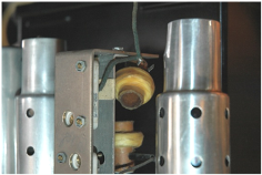
top view of receiver chassis and the electronically restored receiver. Below, one of the IF transformers with one coil not anchored.
|
|
Featured Restoration |
|
one and ordered it, but this meant that I needed 2.5VAC at 12 Amps for the 8-45 triode output tubes. Two 6 Amp transformers were also ordered.
With my 4” speaker connected I injected an audio signal at the grid of the 45 output tubes, all was fine. I moved the signal to one grid of the push-pull drivers 42 tube, still all was fine. I then went to the 2nd audio grid, still fine, then to the 1st audio grid, nothing. After much searching I found the wiper of the volume control shorted to ground. Someone in the past had done a poor soldering job and put a large lump of solder on the terminal which shorted against the chassis. With that fixed I injected a modulated RF of 485kHz. into the grid of the oscillator/mixer and aligned the IF. The IF transformers are very a cleaver design; if you check the picture above you see the primary coil, the one that feel free and caused the short and it’s above the secondary coil, the secondary coil moves up and down driven by a cam and causes the coupling and consequently the IF bandwidth to change. This works very well but does effect the IF gain.
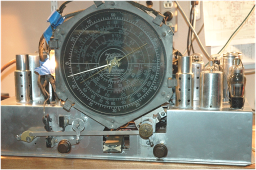
With the IF peaked up nicely the radio didn’t play on the broadcast band but worked fine on all the short wave bands, 4-6 uV for -0.2 Volts of AGC voltage. The broadcast band wasn’t working because the local oscillator wasn’t oscillating. I checked the 6A7, it was fine, checked voltages, and checked for shorts. On the shortwave band there was 3.2V on the cathode of the 6A7 and 4.6V when the broadcast band was selected, no oscillation. Finally, in desperation I removed the oscillator coil can [note the chassis top view it’s the can nearest the front of the chassis next to the tuning capacitor]. The oscillator coil former is a 1” ID 5” long phenolic tube; coils wound on the outside, unfortunately a mouse had built a nest inside the coil former. I gentle pulled out the nest, it was material like course cotton. With the nest removed I could see from the top coil two AWG30 wires [broadcast band] twisted together and bare from the mouse activities. I separated the wires and coated them with insulating dope and powered it up again. The broadcast band worked now but with very poor sensitivity.
I decided to remove all RF coil cans and inspect for mouse activities. What a job to remove the nuts under the chassis, it took me the better part of an hour to remove, inspect and replace the three coil covers. With the RF coil cans off the broadcast band worked somewhat better but not well. Then I found the problem. There’s a padder capacitor in the broadcast band oscillator circuit and is used to balance the dial to oscillator tracking. When I turned the adjustment screw there was just a lot of noise. I removed the padder cap and found one set of plates not soldered and in the adjustment screw area the ceramic was full of chrome flakes and media beads. More about the media beads later.
The radio chassis was originally chrome plated and that has failed badly, now there are chrome flakes floating around everywhere and in everything. Even after blowing everything out with compressed air chrome flakes still keep showing up in everything and shorting things out. E.H. Scott did it the right way, they copper plated chassis first, which Zenith did, then they nickel plated the chassis which Zenith didn’t and the Scott chrome plated only the top of the chassis. We talked about brushing the loose chrome off and painting the good chrome areas to stop the flaking. I found that an air blast while brushing did a good job and no additional chrome flacks appeared.
After reassemble of the padder capacitor, RF cans still off the RF amps appeared to be working fine. I removed the grid caps from the two RF amps and put all RF can covers back on but when I went to put the 1st RF grid cap back on I found the cap unglued and not connected to the grid. I took a 6D6 from the meter amp to replace the dead 1st RF, with another 6D6 installed, the 1st RF is working fine; now onto the alignment.
As I stated before, the broadcast band this radio has a variable padder |

|
capacitor used to balance the calibration of the dial to the local oscillator. Zenith’s procedure is to set the dial to around 600kHz. with the modulated RF generator at 600kHz., then rock the tuning back and forth while adjusting the padder for maximum modulated audio. Then they want you to set the dial and RF generator to 1,400kHz. and adjust the local oscillator trimmer till the dial is at 1,400kHz., then back to a recheck of the 500kHz. calibration. I then peak the two RF stage trimmers for maximum AVC voltage. I used an analog volt meter on the AGC bus and my old calibrated General Radio 1001A RF generator.
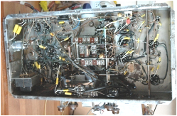
With about 24 man-hours in the receiver chassis restoration so far, I moved onto to modifying the power supply chassis that I had miss designed. The one power transformer I had originally specified for the radio chassis B+ was rated to 90mA and I had to use an 80 rectifier but the radio chassis actually draws 150mA at 300VDC. The new power transformer and two filament transformers arrived from Antique Electronic Supply in two days. The new power transformer can handle receiver load and the required 5Z3 rectifier.
I broke the bolt on my ½” Greenlee punch and had to go to 5/8” for the transformer leads hole, in installing the new power transformer, the chassis steel is very thick. Installed the 2-2.5VAC filament transformers on the rear apron, and paralleled the two secondary’s; good to go now.
I had the two 12” Jensen speakers but they have metal [iron] filings in the voice coil gap 9no comment on how the filing got there) and need to be cleaned before putting power to the field coils and audio to the voice coils. I have a 10” 2-way book-shelf speaker so I connected it up to output transformer for a listen. I was amazed, this Stratosphere sounds really good; it has plenty of bass, plays loud and sounds great.
Zenith Stratosphere 1000Z Restoration the Final Stages I was asked about the flaking chrome problem; the story is that the receiver chassis was plated chrome on copper over steel. The chassis had a little rust but the chrome/copper plating had started to peel off. Inside the chassis was no different; I tried blowing off the flakes with compressed air only to start new areas peeling. I decided to leave well enough alone and just brush off the loose flakes.
Now about the media beads; some of you have restored cars and used media bead blasting to remove the paint, along with the rust and Bondo from an old car’s body. This Zenith chassis had badly failed chrome so with upper and lower chassis components still in place, he masked off the components on top of chassis and then had the chassis blasted with media bead. The media beads, about 15mils in diameter got into every unprotected crevice and hole, including the broadcast band padder variable trim capacitor along with the planetary tuning gear which acts a tuning reduction unit. I have now added media bead blasting to the list of things not to do to electronic equipment, along with WD40 for cleaning switches and carbon controls.
Because the receiver power supply transformer got hot while on for four plus hours, I got the stock Hammond 300VAC 250mA power transformer to replace the 150mA transformer. After placing a few more strategic holes in the PS/Amp chassis it was mounted, wired up and working fine. The two DC power supplies are now 300VDC at 150mA for the receiver chassis and 330VDC at 250mA average for the power amplifier. I ran the full radio, with the two 12” and 5” Jensen speakers for over four hours and the two power transformers got warm but not over 140° F in my 95° F workshop. A short recap: the PS/Amp (power supply amplifier) now has two power transformers, one 10H 150mA and one 10H 300mA filter chokes, two 8mH 2A line filter chokes, two 2.5VAC 6A (12A total) filament transformers, one 50W audio output transformer; that’s a lot of Hammond iron and copper in this Stratosphere’s power supply and audio amplifier. |