


|
Complete Radio Service and Speedy Too. |
|
Majestic Radios |
|
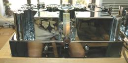
The receiver chassis fully assembled and ready for RF and IF alignment. |
|
EH Scott Allwave 12 Deluxe Restoration |
|
bands. The upper frequency band uses a lower capacitance variable capacitor, one on either side of the dial. See the picture. The large turret assemble contains the RF plate tuned tanks and local oscillator coils only. The antenna input is inductively coupled but uses no Faraday shield like later Scott radios, Phantom and Philharmonic. The mixer stage is a 58 pentode tube with the mixer section driven by a 56 triode local oscillator circuit. The RF amplifier plate (mixer grid) tuned circuits and the local oscillator coils are located on a large rotating radial coil and electrical contact assembly. The bottom plate that covers the movable coil assemble and along with the underside of the chassis provides the only shielding.
The IF frequency is 465kHz. and is peak aligned. There are three (3) 58 pentode tube IF amplifier stages, the plate section capacitive coupled to the next stage. On the underside of the chassis the plate tanks are located in shield cans, the first two IF stages tuned with compression variable capacitors. Then an insulated copper wire, from the plate extends through the chassis to a shielded grid tank with the wire glued to side of the coil, about all the way up the tuned grid tank, that feeds the next IF amplifier stage. This is very unusual way to couple the tuned primary to the tuned secondary of the IF transformers. Standard practice, even in 1932 was to use inductive coupling, the coil spacing and tuned tank “Q” consequentially the IF bandwidth or selectivity. Hammarlund and Zenith 1000Z were using variable inductive coupling to vary the tuned IF bandwidth in the same year, 1934.
The IF output (Grid) tank tuning is made impossible by the design; EH Scott in for some reason put compression alignment capacitors on the top of each of three IF coils but put them under the chrome cans with no access hole for adjusting the capacitors with the can in place. What made the alignment even more difficult, there’s a shielded grid cap wire soldered to the chrome can and passing through a hole in the side of the chrome can. To perform the IF alignment I drilled a hole in the top of each chrome shield can.
The ALLWAVE 12 Deluxe has no BFO for the DX SW CW listening.
The second detector is a Wunderlich tube which is a dual grid triode, allowing the two grids to act as detection diodes and at the same time control of the triodes plate current or audio output. My ALLWAVE 12 Deluxe might end up with a 55 dual diode-single triode tube as 2nd detector and AF amplifier. The final IF transformer secondary has a center tapped winding where the CT contains the audio and AVC voltage, filtered further it’s the AVC DC voltage. In the Wunderlinch circuit the CT feeds the AVC bus only after the filter. The AVC is marginal and later Scott radios like the Allwave 23 used amplified AVC. |
|
The first audio and detector stage is capacitor coupled to the volume control then to the grid of a 56 triode whose plate is connected to an audio choke which is capacitive coupled to the grid of a third audio amplifier. This third audio stage has an audio choke plate load and is connected to the power supply amplifier chassis by the umbilical cable. The third audio stage is capacitive coupled to the push-pull driver transformer which is connected to the grids of the number 45 power triode tubes.
Reassembly and Alignment
Coming soon |
|
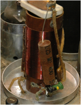
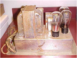
One of the IF transformer upper coil. Below the power supply amplifier as received, lots of rust as was the receiver. |